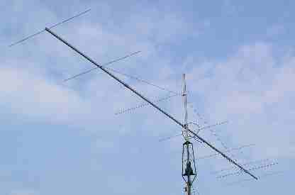
The G4ZTR 4m beam
Introduction
In his article "OPT2 Yagis",
Rainer DJ9BV describes a series of yagis developed by computer optimisation.
They feature high gain, good polar diagrams and near 50ohm impedance. The
article is published in "Dubus Technik V".
The smallest 2m yagi that
Rainer describes is 2 wavelengths long, and turned out to be just what I was
after in terms of performance. However Rainer has no designs for 4m, so I have
scaled the dimensions, applied correction factors where necessary, and checked
the results using "Yagi Optimiser".
The result is a 4m beam with
more than 12dBd gain and a front to back ratio which exceeds 20dB. I have been
encouraged to publish the dimensions here, and it can be copied but remember
that the basic design belongs to DJ9BV.
Construction
My construction is
light-weight, and is designed for portable use, with frequent assembly and
breaking down in mind.
Elements are 3/8 inch 16g
tube
Driven element is 5/8 inch
16g tube
Boom is 1-1/4 inch square
section, 16g.
The elements are mounted
directly above the boom and in electrical contact with it. The mounting blocks
are machined from solid aluminium.
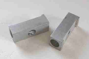
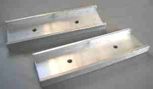
The boom is in 4 sections of
approximately 2m length each. Boom joiners are machined from 1-1/2 inch
channel. There are two things to note about the boom joiners.
Firstly they
cannot be in the same position as an element mount, and secondly, the middle
joiner also functions as a mast clamp point.
It needs to be located slightly nearer to the rear of the antenna so
that balance is achieved.
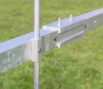
Element fittings use M4
bolts, and the boom to boom clamps use M5. The fitting to the mast uses
conventional pipe clamps, M8 size.
The boom is too flexible
without a means of support. A synthetic rope is used to "hang" the boom from a
central support point a couple of feet above the boom to mast clamp.
The aerial is designed to be
near 50 ohms impedance, which means that either a split dipole can be used, or
a folded dipole with a 4 to 1 balun. For simplicity at present I have opted for
a gamma match feed, so it is not of concern if the actual impedance is a little different.
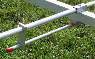
The gamma
match is a one-off for this project and is not described further.
Dimensions
(all in mm - eles 9.5mm except 15mm driven )
Element Noаааа аааа Distance from reflectorаааа Length
Refааааааааааааааааа ааааааааааа 0ааааааааа ааааааааааааааааааааааа ааааааааааа 2080
Dipoleаааааааааааа ааааааааааа 675аааа ааааааааааааааааааааааа ааааааааааа 1970
1ааааааааааааааааааааа ааааааааааа 1100аа ааааааааааааааааааааааа ааааааааааа 1945
2ааааааааааааааааааааа ааааааааааа 2210аа ааааааааааааааааааааааа ааааааааааа 1915
3ааааааааааааааааааааа ааааааааааа 3765аа ааааааааааааааааааааааа ааааааааааа 1880
4ааааааааааааааааааааа ааааааааааа 5530аа ааааааааааааааааааааааа ааааааааааа 1860
5ааааааааааааааааааааа ааааааааааа 7285аа ааааааааааааааааааааааа ааааааааааа 1850
6ааааааааааааааааааааа ааааааааааа 8740аа ааааааааааааааааааааааа ааааааааааа 1870
ааааааааааааааааааааааа ааааааааааа