by N1BUG
This is a modified version of the original article published in "2 Meter EME News", Issue #43, November 1993.
In the past, whenever someone wanted information on the EME polarization issue I have referred them to the article by KL7WE1. However, as that article is not so easy to find, and because I have been collecting some statistical data to back it up, perhaps this is as good a time as any to re-visit the issue.
I find it is usually best to start by stating the obvious and then progress to the not so obvious stuff. It should be obvious that EME signals can be heard best when the incoming signal polarization matches that of the receiving antenna. As the difference between the polarization of the signal and that of the receiving antenna increases, the signal weakens until the polarization difference reaches 90 degrees. With a 90 degree difference in polarization the signal loss is something in excess of 20 dB for most antennas. A formula for the loss of signal strength due to polarization misalignment is
Loss(dB) = 20 log(cos(offset angle))
This works well until the polarization angle approaches 90 degrees, but some correction factor should be applied in practice for angles near 90 degrees to prevent the result from approaching infinity. Real antennas do not have infinite rejection of the opposite polarization.
Perhaps equally obvious is that the polarization of EME signals often does not match that of the receiving antenna and therefore are not heard as well as we would like (or not heard at all). Usually Faraday rotation takes all the blame for this situation. How often have you heard someone say "I did not work that station... the Faraday was bad!"? Most of us are aware of the basic principle of Faraday rotation -- a shift in the polarization of a signal as it passes through an ionized region. But there is another, equally important factor which has much to do with the polarization of EME signals -- that is spatial polarization offset. While one often hears terms such as "spatial offset" and "spatial polarization" it is apparent that not everyone has a good understanding of just what it is or how it works. Ask several EME'rs about it and you will probably hear things like "it's the polarization difference caused by Faraday". In fact is has nothing to do with Faraday rotation, but working together with Faraday it can cause big problems.
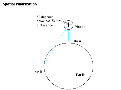
Even if there were no such thing as Faraday rotation, we would still have problems caused by spatial polarization offset! Simply put, spatial polarization offset is a difference in polarization between two stations based on simple geometry. Suppose you had a large ball (call it Earth) in front of you and you placed two antennas one it -- one on the top (be sure to align the elements so they are parallel to the surface of the ball directly below the antenna) and one on the left side (again you should align the elements so that they are parallel to the surface of the ball directly "beneath" the antenna). See figure 1. If you project a signal from each of the two antennas toward some distant object (let's call it Moon) you will see that there is a 90 degree difference in polarization even though both antennas are horizontally polarized with respect to the patch of Earth over which they stand. This polarization difference is the spatial polarization offset.

Figure 1 -- What Spatial Polarization Offset is (a little over-simplified...)
                                sin L * cos E - cos L * cos A * sin E
          P = ArcTan (  --------------------------------------------------------  )
                                              cos L * sin A


          where   L = latitude of the station
                  A = azimuth of antenna
                  E = elevation of antenna
                  P = polarization angle with respect to Earth's polar axis
The spatial polarization offset between two stations is simply the difference between the spatial polarizations of the two stations or P1 - P2. For convenience it is a good idea to do some additional computation to keep the offset in a 180 degree range, either from 0 to 180 degrees or -90 to +90 degrees. If you rotate a yagi 180 degrees in the polarization plane, after all, you end up with the same polarization you started with. Therefore a range of 180 degrees is sufficient to describe any polarization angle.
Here is where things start to get complicated. Did you ever wonder where those polarization loss numbers often given by moon tracking programs come from? Often they come right out of the two equations above, first by finding the spatial polarization offset between two stations and then using equation 1 to reference this angle to dB loss. That sounds OK until one remembers that Faraday rotation exists! With Faraday messing things up (by shifting the polarization of the signals in transit), we can't assume that the polarization difference between a signal arriving at an antenna and the antenna polarization is equal to the spatial polarization offset between the transmitting and receiving stations, can we? No, indeed! So of what use are these dB loss numbers from such programs? Not much! At this point it becomes tempting to assume that if Faraday can mess up any calculation of polarization offset (at least in terms of what the polarization of the signal will be when it arrives at the receiving station), there is nothing at all to be gained by considering spatial polarization offset. That's not true, and now I will attempt to expain why.
Here we have two factors which affect the polarization of EME signals. One of them (Faraday rotation) we can not yet predict using practical methods, but the other (spatial offset) is easily calculated. Fortunately, by having some degree of control over one of these factors we can significantly reduce the adverse affects of the two factors combined. To understand how, we must examine what happens with some typical combinations of polarization shifts due to spatial offset and Faraday. But first it is important to know that due to the anisotropic nature of the ionosphere a wave front which shifts polarization in a given direction on its way out from Earth will rotate the same amount in the same direction (from an Earth- bound observer's perspective) on the return trip. Huh??? What's that again? This means that if you could stand behind your antenna and see the polarization of the signal leaving that antenna, travelling to the moon and back again, you would observe the same rotation twice -- once on the outward trip and once on the return trip. Thus, if the signal rotated 30 degrees clockwise (from your perspective) on its way to the moon, it would rotate 30 degrees clockwise again on the way back to Earth, arriving 60 degrees clockwise shifted from the polarization of your antenna. Keep this in mind while considering the following.
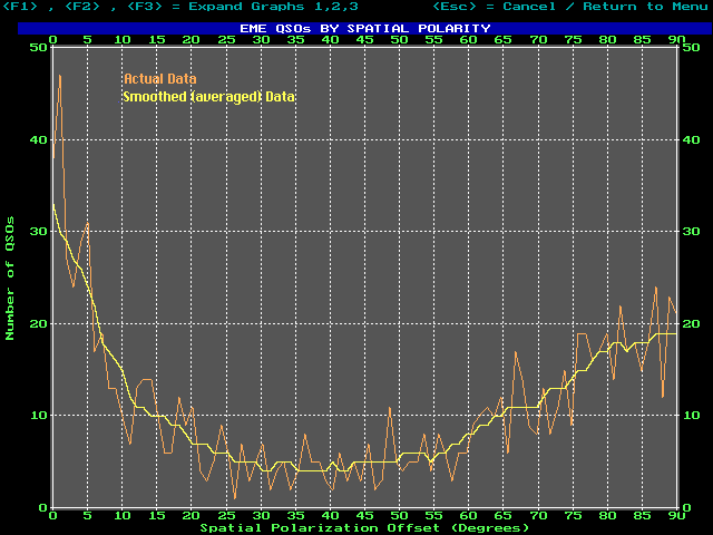
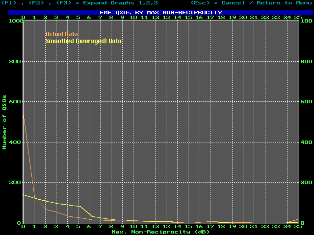
Spatial Offset 0 DegreesThere are literally thousands of possible combinations, but the simple cases just examined give a good idea how certain combinations of spatial offset and Farday can make it much more difficult to complete an EME QSO. Statistics bear this out. See fiures 2 and 3. Even when operating random, more contacts occur when the spatial offset is near 0 or 90 degrees than when it is in the area around 45 degrees. Further detailed analysis of EME contacts shows that even on paths that are dominated by spatial offsets near 45 degrees, most of the QSOs occur during the occasional times when the offset does approach 0 or 90 degrees.

Figure 2 -- EME QSOs vs. Spatial Polarization Offset

Figure 3 -- EME QSOs vs. Maximum Non-Reciprocity
Another way to look at this is to think in terms of "window of opportunity". As pointed out in the examples above, when the spatial polarization offset is 0 or 90 degrees, Faraday can vary over quite a wide range without causing large signal loss for either station. In either of these cases, Faraday of +/- 30 degrees (a 60 degree range) from ideal will result in a maximum loss of 1.75 dB. This is a substantial "window of opportunity" for completing a QSO. When the spatial offset is 45 degrees we're already looking at 3 dB loss for reciprocal conditions and a very slight shift in Faraday (+/- 15 degrees) will double that figure to 6 dB in one direction. Thus a very small "window of opportunity" as the Faraday shifts occur.
It should be pointed out that there are several situations when good EME QSOs can be made when the spatial offset is near 45 degrees. One obvious case is when the two stations have enough power and antenna gain to overcome significant loss to to polarization misalignment. Especially during one hour long skeds, the Faraday may go through several large shifts, and even though conditions at a given time are one-way it is possible to complete as it sweeps back and fourth between station A hearing B and vice versa. The other possibility is that the polarization may not always be perfectly linear. Polarization could (and probably does) sometimes get distorted going through the ionosphere and end up elliptically polarized or fragmented into several distinct linear polarizations. In this latter case almost anything could result, though some loss of signal strength is likely. Of course there will also be times when the spatial offset is near 0 or 90 degrees and we don't make the QSO. However the odds are clearly better when the spatial offset is in our favor.
The point is this: if it can be shown statistically that it is easier to make EME QSOs when the spatial offset is not in the vicinity of 45 degrees, why not try to avoid making skeds when the offset is bad? Statistics show that it will improve our chances of success quite substantially. I'm not saying one should refuse a sked at 45 degrees spatial offset if that is the only time available, but why not choose a better time when it is possible? I attribute my past success on EME in large part to an understanding of the polarization problem and careful scheduling to maximize my completion rate.
The following general rules of thumb may be helpful.
Programs that do not keep the spatial offset in a range of + or - 90 degrees will be more confusing to use for this purpose, but hopefully most software today does not suffer from that problem. It is easier to shedule according to maximum path non-reciprocity (compared to looking at spatial offset directly) but even today many programs do not give this information. If you are using software which provides the maximum non-reciprocity data, you can easily come up with your own guidelines for scheduling based on your experience. For example, you might decide it is best to schedule single yagi stations only when the maximum non-reciprocity is no more than 1.5 dB, but 4 yagi stations are OK up to 6 dB. If you can't find a time with good polarization to the station you want to work on a given day, try another day. Often, the declination of the moon plays a large role. For example, good spatial offset from central Europe to the northeastern U.S. only occurs when the declination is greater than +10 degrees. At lower declinations, the antenna aiming angles are not correct to allow favorable polarization offsets (and reciprocal conditions).
Perhaps someday we will be able to calculate both spatial offset and Faraday rotation in real time, but for now all we can do is maximize our chances using the best of current technology. Understanding spatial polarization offset and its interaction with Faraday rotation is a big step and can significantly improve success ratios.
References:
1. "Spatial Polarization and Faraday Rotation"; Tim Pettis, KL7WE. Proceedings of the 22nd Conference of The Central States VHF Society (Lincoln, Nebraska 1988).
2. "Taking a Closer Look at Faraday"; C.H. Hustig, MSEE. 432 And Above EME News, November 1984. (Formula was later revised by Mr. Hustig to include antenna elevation. Corrected version used here appeared was published in the KL7WE article).
![]()