
Simple Elevation (or Azimuth) Indicator
An improved version of the circuit has been added.... see below.
Several years ago when I built my first EME array, I needed some simple and inexpensive way to read out the position of the antenna in both azimuth and elevation. My rotators did not provide this function so I would have to build something. I searched through old books, magazines and newsletters. I found several designs, but most of them were undesirable for one reason or another. Many required precision mechanical alignment of parts at the antenna, or special 1:1 mechanical coupling to the mast, or expensive components. Then I found an article by W7IUV in the April 1983 Lunar Letter. This was just about ideal as it would work for either azimuth or elevation (build two and you've got both), needed no expensive or hard to find parts, and was very simple to put together and calibrate. In the years since then I have continued to look at other methods of accomplishing this, but the W7IUV method is still hard to beat... and I am still using it.
You will need a potentiometer mechanically coupled to the antenna to act as the position sensor. This must be a linear taper pot. Value can be anywhere between 500 ohms and 10K ohms! For elevation, I use a 2 or 4 watt, 3/4 turn wirewound pot mounted in a plastic jar attached to the antenna with a weighted pendulum attached to its shaft. This has consistently given accuracy of +/- 3 degrees, and would no doubt do better with a precision one turn pot (if I could afford one I would try it). For azimuth I use a precision 10 turn pot coupled to my rotator in such a way that it rotates 3 turns or more for 360 degrees of antenna rotation. See pictures below. Cough up the money for a good 10 turn pot (about $15 to $20) for the azimuth. Otherwise errors may be too large. This circuit will hold to about +/- 2 or 3 degrees with a good pot and proper mechanical coupling to the antenna. If your antenna requires more precise aiming than this (at least on VHF bands) then you probably can afford a more elaborate readout for it anyway.
You will also need a multiturn trimmer of the same value as your position sensor pot, and one that is about 10 times the value of the pot. Example: if you are using a 1K ohm pot at the antenna you will need a 1K and a 10K trimmer. These will be your "zero" and "full scale" calibration adjustments. If you do not have multiturn trimmers, regular 3/4 turn ones will work but they are a bit touchy to adjust. 15 turn trimmers are less than $2 apiece and make adjustment very easy.
You will need something to use as a meter for the readout. This can be any micro- or milliammeter with a full scale sensitivity of up to 1 mA, or it can be a digital voltmenter with a 1 to 5 volt full scale sensitivity. In the case of analog meters, it is nice to use a 0 to 100 uA meter for elevation, since you can calibrate it to read elevation directly in degrees (90 uA = 90 degrees). For azimuth, digital meters are great. I recently (late 1999) got two digital, backlighted LCD digital panel meters from Hosfelt Electronics for something like $8 each. They make wonderful azimuth and elevation readouts!!! [I will try to get a picture of my antenna control unit using those readouts here soon]
Other than that you just need a source of regulated dc voltage in the 5 to 15 volt range. The exact value is not important, but it is important that it be well regulated with little or no variation over time. I like to use a three terminal regulator such as a 7805 or 7809 running off some convenient 12V supply. I do not recommend using a zener diode regulator as they tend to not be stable enough with temperature variation.
Here is the basic circuit:
All of the parts except VR1 are in the shack. VR1 is at the antenna. You will need a three conductor cable going to the antenna to connect VR1. [note: if you already have a ground conductor running to the antenna, you may tie the ground of this circuit into that and you will only need two additional wires. Also if you are going to use two of these, for azimuth and elevation, you can run the +vdc to both pots through the same wire].
VR1 is mechanically coupled to the antenna. It can be 500 ohms to 10K ohms.
VR2 is the "zero" adjustment trimmer. Its value should be the same as VR1.
VR3 is the "full scale" adjustment trimmer. It should be roughly 10x the value of VR1.
Improved version
The original design works well for small and medium sized arrays, and allows the use of inexpensive analog meters,
especially for elevation. However, there is some non-linearity. Thanks to Mark, EA8FF, for the following information...
I just did some calculations on the circuit like I was first using it: 10k potmeter in one leg, 10k trimpotmeter in the other and 100k pot to adjust full-scale. In this case the 359 to 360 degree division is abt 6.2% larger than the 0 to 1 div. This is due to the loading of the bridge by the 100k potmeter. If the fullscale potmeter would be 1Mohm,the difference drops to 0.6%,so I think the value of the circuit loading the bridge must be like 500 times the AZ potmeter. Anyway there will allways be an error due to nonlinearity. Yes I modified the circuit with the potmeter in the +V line and my instrument has several Mohm internal resistance. The error at the moment seems to be 1 degree,but I dont think I can do better because this is the sum of all mechanical and electrical errors in the whole system plus the uncertance of the last digit of the DVM.
Below is the improved circuit. Component values can be the same as in the original version (above) and the adjustment
procedure is the same. If the full scale reading is too high and cannot be reduced enough with VR3, try using a
lower voltage into this circuit. Or, if you are certain that its output will remain stable enough, use an adjustable
voltage regulator to feed this, and eliminate VR3 (in this case, adjust the regulator output voltage to set full
scale). The meter must have a high input impedance (the higher the better).
Calibration:
Once you have this hooked up, set both VR2 and VR3 to midrange. Set your antenna to zero degrees (north for azimuth,
on the horizon for elevation). Adjust VR2 for a zero reading on the meter. Now move the antenna to its opposite
extreme (360 for azimuth or straight up for elevation) [note: if the meter reads backward or negative during this
step, simply reverse the leads to the meter... notice I did not label them + and - in the first place!!] and adjust
VR3 for the proper reading on the meter. That's it, you're done.
Mecanical Stuff...
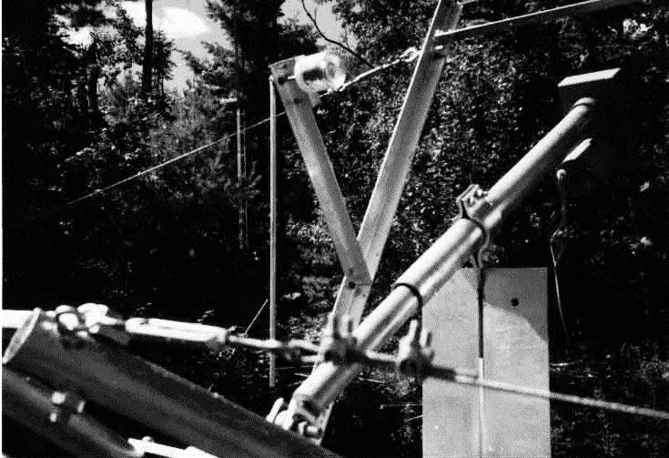
Here are a couple of photos showing elevation and azimuth sensor pots mounted on an array... your implementation
will probably be different but maybe these will help...
Well, this one wasn't exactly an array yet when the picture was taken :-)
But this is a photo of a pot for elevation sensing (mounted in the plastic jar) with a pendulum.
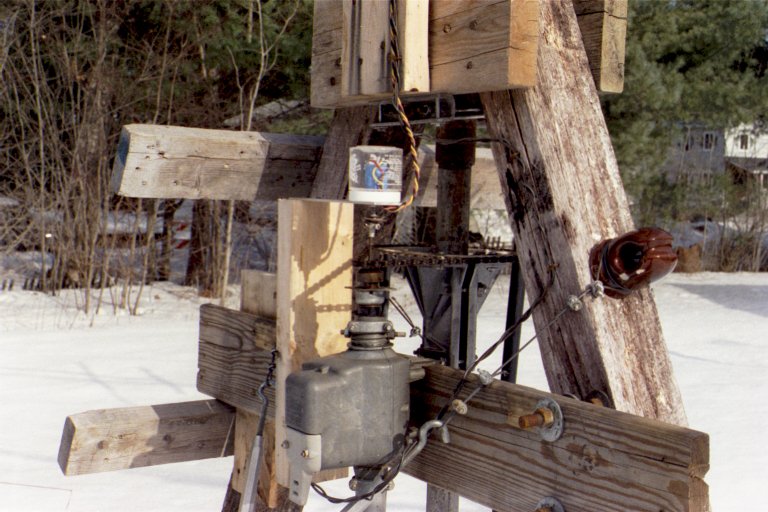
And here is an example of a 10 turn pot used for azimuth sensing. This one turns about 6 turns for 360 degrees
of antenna movement.
![]()